| |
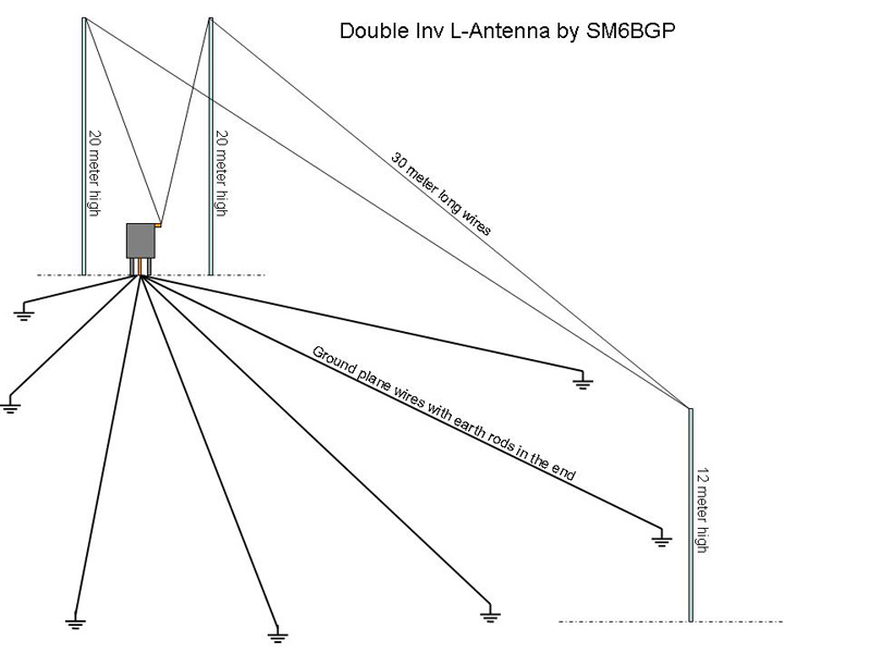
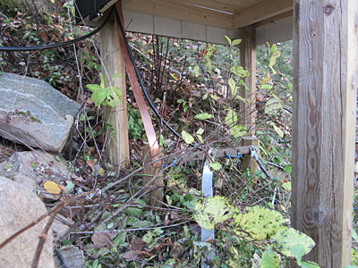
Simple antenna layout with the little coil-house in center of the picture. The ground plane wires are of varying length adapted to the size of the house garden. A lot of metal is digged into the ground for better take off for the radio waves.
This antennas fundamental frequency is 1260 kHz without coils and capacitors. |
 |
 |
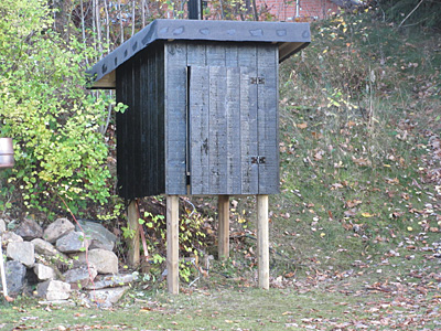
The little coilhouse where different frequencies are tuned in. |
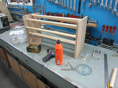
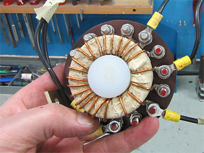
Coil for 136 kHz takes form. |
 |
 |
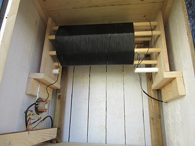
Coil for 136 kHz ready and dimensioned for single wire inv-L. |
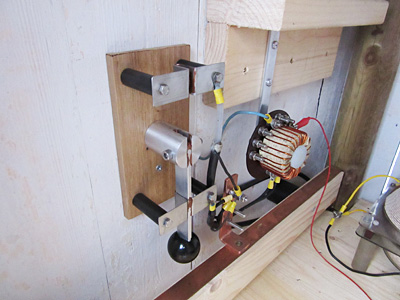
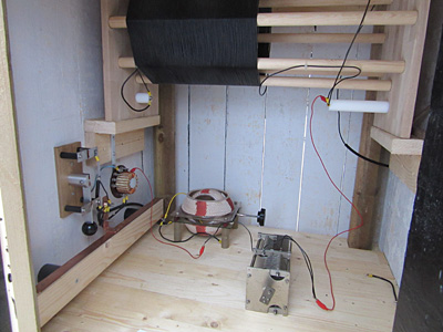
Impendance tranformer and cable switch. |
 |
 |
Impendance tranformer. |
Earth connections via copper plate. |
 |
 |
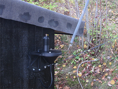
Antenna connection outside the coil house. |
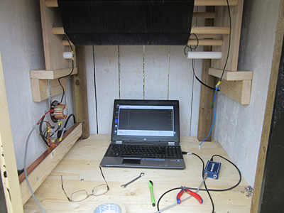
Handy little coil house for antenna measurements. |
 |
 |
When to work at 150 meter I add some capacitance.
136 kHz coil at top, with less turns for double L-antenna. |
Antenna connector outside the coil house. |
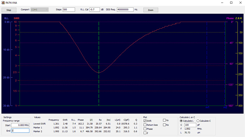 |
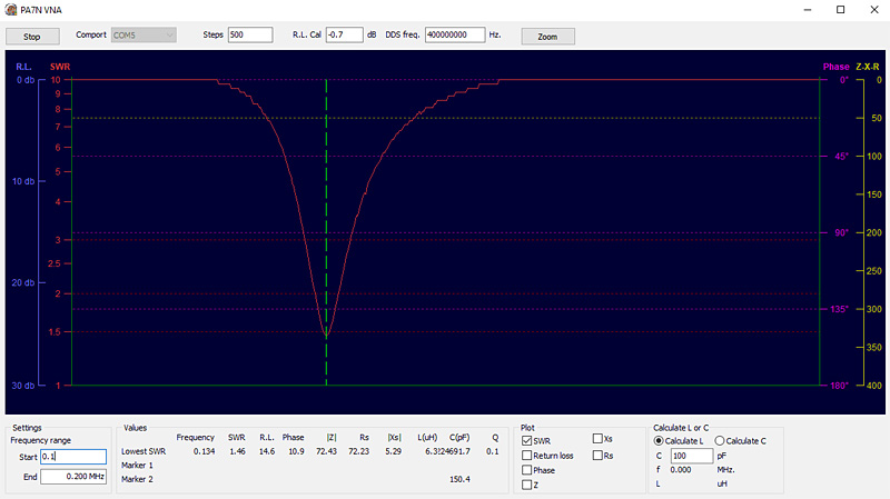
This picture shows data from the fundamental frequency without accessories, 1261 kHz. |
 |
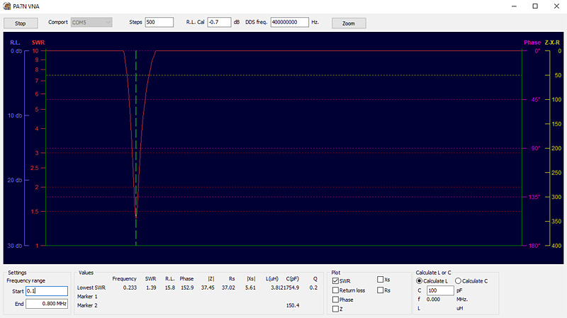
This picture shows data when the big long wave coil (2.225 mH) is added, but no transformer. |
 |
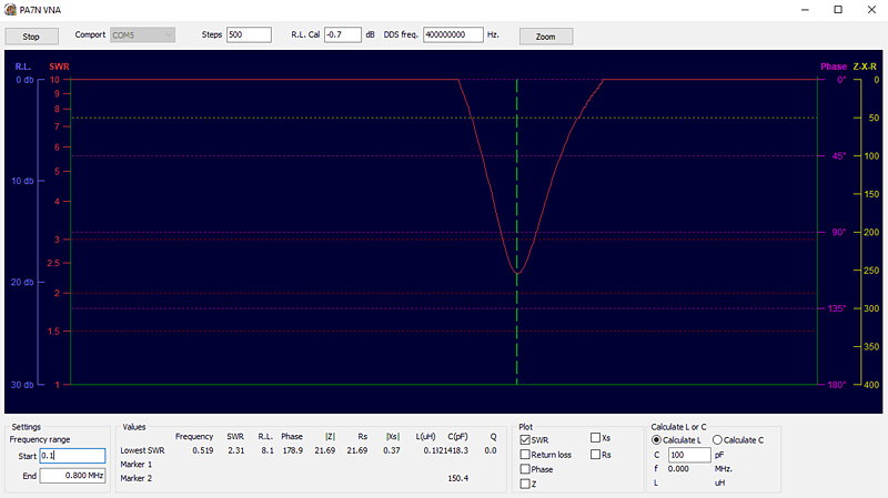
This picture shows data when the variometer is added with maximum inductance, 679 uH = 233 kHz. |
 |
This picture shows data when the variometer is added with minimum inductance, 119 uH = 519 kHz.
To work on 472 kHz I have to adjust the variometer to approximately 130 uH and of course use the transformer. |
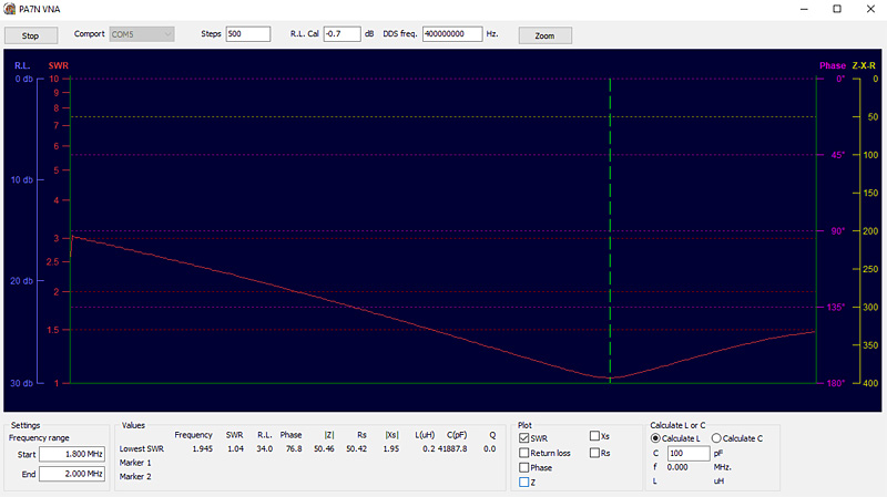 |
This picture shows data when the variable capacitor and transformer is added, approximately 229 pF of capacitance.
The antenna seems to work very well also at our 150 meter band!
|
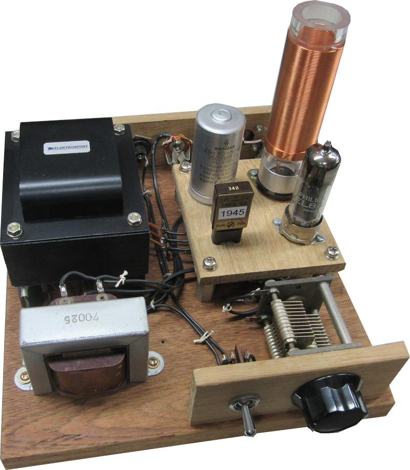 |
Picture of my little woodie, with just one EL84 tube and a modulation transformer from an old radio.
Just for fun I use this little wonder on 1945 kHz with AM modulation. Output is about 3-4 Watt. |
| |
|